
Line vs Load Wiring
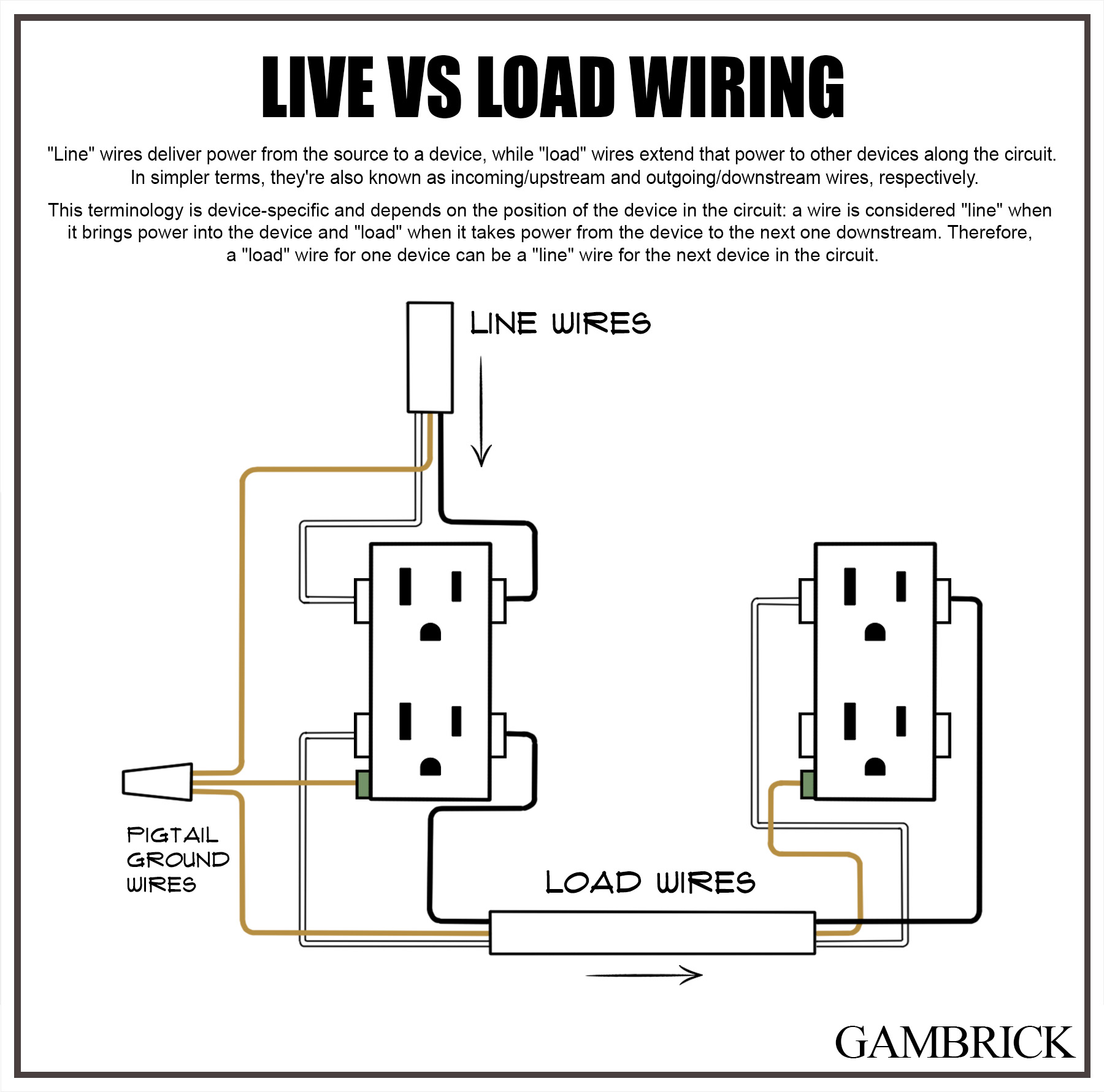
In the electrical industry, “line” and “load” wiring describes the function of wires. “Line” wires deliver power from the source to a device, while “load” wires extend that power to other devices along the circuit. In simpler terms, they’re also known as incoming/upstream and outgoing/downstream wiring, respectively. This terminology is device-specific and depends on the position of the device in the circuit: a wire is considered “line” when it brings power into the device and “load” when it takes power from the device to the next downstream device. Therefore, a “load” wire for one device can also be a “line” wire for the next device on the circuit.
The line and load concept applies throughout different parts of an electrical system.
- “Line” wires feed electricity, and “load” wires move it along a circuit to other devices. A line wire carries power from the source to another device.
The line wire carries incoming electricity while the load wire carries outgoing electricity.
- The “Line” wire is the hot wire that comes directly from the power source, such as the electrical panel, to other devices, including outlets and switches. The “Load” wire carries power forward from one device to another along the circuit.
It’s important to understand that a wire can be a “line” wire for one device and a “load” wire for another.
For example, lets examine a circuit with two outlets labeled A and B. The wire supplying power to outlet A is its “line” wire; the wire exiting the outlet to supply power to outlet B is its “load” wire. However, wire A’s “load” wire becomes wire B’s “line” wire, because its supplying power to the outlet.
Line vs Load Wires
Line wires supply power to a circuit; they’re also known as upstream or incoming wires. Load wires carry power along the circuit to more devices, they’re also called downstream or outgoing wires. In many cases, a line wire for one device can also be a load wire for the next device along the circuit.
Consider the following example circuit in a typical home that powers a series of outlets:
The circuit starts at the main electrical panel and circuit breaker. The wire leading from the circuit breaker to the first outlet is the “line” wire. It carries electricity from the power source (breaker) to the first outlet.
Next, another wire, the “load” wire, carries power from the first outlet to the next outlet downstream along the circuit.
In this setup, the “load” wire of the first outlet becomes the “line” wire for the next outlet in the sequence. This pattern repeats until the end of the circuit.
The electricity essentially hops from outlet to outlet via these load and line wires, always arriving via a line wire, and then leaving to the next outlet via a load wire.
So, in cases when wiring a circuit with multiple devices, a line wire for one device can be a load wire for another.
What is a Line Wire
A “line” wire is a term used in the electrical industry to refer to the wire that carries power from the source to a device or an appliance. This wire is responsible for bringing electricity into the device or appliance in the circuit, serving as the primary conduit for power.
For example, consider a circuit supplying power to a series of outlets in your home:
- The circuit starts at the main service panel, where the circuit breaker or fuse is housed.
- The wire leading from this circuit breaker to the first outlet is the “line” wire.
- Any wire powering a device is considered its line wire.
In essence, the line wire is the “incoming” wire. It’s the electrical lifeline that brings power from the source (like a circuit breaker or another outlet or switch) into a device, such as an outlet or a light fixture.
It’s important to note that the “line” wire is always live when the circuit breaker is on, and it should be handled with care during any electrical work.
What is a Load Wire?
A “load” wire is an electrical term referring to the wire that transports power from an initial device to other devices downstream in a circuit. It serves as the outgoing route for electricity, allowing power to flow onward in the circuit.
Let’s consider a simple example with a series of outlets:
- Inside the first outlet box, there are typically two sets of wires. One is the “line” wire that brings power into the box.
- The other is the “load” wire, which carries power from this outlet to the next outlet downstream in the circuit.
In this context, the “load” wire of the first outlet becomes the “line” wire for the next outlet in the chain. This pattern continues until the end of the circuit.
The load wire is the “outgoing” wire, serving as the power conduit from one device to the next along a circuit. When working with wiring, remember that the “load” wire may be live if the upstream devices are on, and it should be handled with care.
What’s the Difference Between Line and Load Wiring?
The difference between line and load wiring is that line wires supply incoming power while load wires supply outgoing power to the next device along the circuit. However, a load wire from one device is also considered a line wire for the next device.
When you look at an outlet, switch, fan, appliance, etc., that’s wired on a circuit, the wire supplying power the device is the line wire, while the wire exiting the device and supplying power to another device is a load wire.
Electrical devices generally have a line and a load side unless they’re not supposed to be installed as part of a circuit.
The power supplied by the utility company enters the electric meter through the “line” side. From the “load” side, it exits the meter and enters the “line” side of a disconnect or service panel.
The service panel hosts both line and load connections. Here, the “line” supplies power to the main breaker, while the individual branch circuit breakers act as the “load” in relation to the main breaker. This means that the main breaker sends power to these branch breakers, similar to how the original “line” wire supplies power from the meter.
How Line & Load Wires Function on a Circuit
Outlets, switches, light fixtures, and other electrical devices are often connected in groups on a single circuit. In this setup, the “line” is the wire that runs from the service panel to the first device, while the “load” is the wire extending from this device to the next downstream device.
At the second device, the “line” is now the incoming power from the first device. The “load”, meanwhile, is the wire carrying power onward to the third device, and so forth.
This terminology also applies to the devices themselves. The “line” side of an outlet is where the incoming power is connected, while the “load” side is where power exits the device or electrical box, continuing along the circuit.
How Do I Tell Line vs Load Wire
Identifying whether a wire is the “line” or “load” can be a bit tricky as the physical appearance of the wires is often similar.
Here are some steps and tips to help:
- Power off: Always start by turning off the power at the circuit breaker to ensure safety.
- Check the connections: Typically, the “line” wires come directly from the service panel (breaker box), while “load” wires connect devices downstream in the circuit to the first device.
- Use a voltage tester: After turning the power back on, you can use a voltage tester or multimeter. The “line” wire will show voltage as it’s directly connected to the power source. The “load” wire will show no voltage if it’s disconnected from the downstream device.
- Look for labels: In some devices like GFCI outlets, the terminals for line and load wires are specifically labeled. The LINE terminals connect to the power source, and the LOAD terminals link to the rest of the circuit.
Remember, if you’re ever unsure, it’s best to consult with a professional electrician. Misidentifying these wires can lead to device failure and potential safety hazards.
Line vs Load Wires in an Electrical Panel
Determining the “line” versus “load” wires in an electrical panel involves understanding their placement and labeling:
- Observe the panel: In your electrical distribution panel, the incoming feed from the power company, which is the “line,” is usually connected at the panel’s bottom. The “load” wires, or outgoing lines, are connected at the top.
- Follow the standard: This positioning of line and load wires at the bottom and top respectively is typically maintained across various electrical devices in your home.
- Look for labels: Some devices might be explicitly marked with “line” or “power,” indicating the incoming electricity.
- Note the screw color: In certain cases, the “line” wire might be connected to a device using a silver-colored screw to differentiate it from others.
Always remember, safety comes first. If unsure, consult a professional electrician to avoid any possible mishaps.
Line vs Load Wires on a GFCI Outlet
When wiring ground-fault circuit-interrupter (GFCI) outlets, the terms “line” and “load” take on a unique significance. GFCIs feature two pairs of screw terminals labeled LINE and LOAD.
Connecting wires only to the LINE terminals provides GFCI protection solely for that specific outlet. However, wiring to both the LINE and LOAD terminals (utilizing two sets of electrical cables or pigtail wires) extends GFCI protection to the initial outlet and any additional standard outlets downstream on the same circuit.
Why Understanding Line vs Load Wiring Matters
Understanding the difference between “line” and “load” wires is critical for safety and proper operation of certain electrical devices. Correctly identifying line and load wires helps the proper current flow through your circuits to your devices. If you incorrectly identify line and load wires, the current won’t flow properly through your circuit, which could cause damage to your equipment or pose a safety hazard.
There are several instances when it’s necessary to determine a line wire from load wire. These include installing, replacing, and troubleshooting devices like GFCI outlets, light switches, and dimmers.
Here are some examples when understanding line vs load wiring is a must:
- Light switches and dimmers: These won’t work properly if the load and line wires are mixed up.
- GFCI: When installing a Ground Fault Circuit Interrupter (GFCI) outlet, correct wiring is crucial. A GFCI contains an internal circuit breaker designed to cut power in the event of a fault. If the wiring is incorrect, a short may cut off the power from the source (upstream), but it won’t interrupt the power flowing to the other devices (downstream) on the “load” wire. This malfunction can fail to prevent accidental electrocution, posing a significant safety risk.
- Troubleshooting: When troubleshooting an electrical issue, knowing where the line and load wires are located helps determine whether the power is reaching the device.
Understanding line versus load wires isn’t just about proper installation; it also ensures the electrical system’s safety in your home.
Does it Matter if Line & Load Wires are Reversed?
Yes, reversing your line and load wires on a circuit can cause problems for your devices and potentially serious safety issues.
Here are a few examples:
- Correct Installation of Devices: Certain electrical devices, such as Ground Fault Circuit Interrupter (GFCI) outlets or dimmer switches, require a specific connection to line and load wires for proper functionality. For instance, in a GFCI outlet, the “line” wire must connect to the “line” terminal on the outlet, while the “load” wire connects to the “load” terminal. This ensures that the GFCI outlet can protect both itself and any downstream outlets from ground faults.
- Safety: Incorrectly identifying and connecting line and load wires can lead to safety hazards. Consider a GFCI outlet again; if the wires are mixed up, a fault in the circuit could cause the upstream power to be cut off, while the downstream power remains active. This can lead to a dangerous situation where the outlet appears to be off, but electricity is still flowing to downstream devices, increasing the risk of electrocution.
- Efficient Troubleshooting: Understanding which wires are carrying power from the source (“line”) and which are moving it along the circuit (“load”) can make diagnosing and resolving electrical issues more straightforward. If a problem arises with a device not receiving power, knowing where the line and load wires are can help determine if the issue lies with the source of power or further along the circuit.
Understanding line and load wiring is fundamental to maintaining a safe, functional, and efficient electrical system in your home. Whether you’re installing a new device or troubleshooting an issue, this knowledge is invaluable.
Tools Needed to Identify Line & Load Wires
Here are a few tools you can use to identify line and load wires:
- Multimeter: A multimeter is a tool that measures electrical voltage, current, and resistance. Its probes connect it to the wires under test, providing precise readings.
- Non-contact voltage tester: It detects live wires without touching them, providing a safe way to identify active circuits.
- Neon screwdriver: A handy device for testing live wires. It glows when it touches an electrified wire, offering a simple visual indicator of power presence.
Each of these tools provides a safe and efficient way to test and evaluate electrical circuits.
How To Identify a Line Wire with a Multimeter
Identifying “line” and “load” wires is key in any electrical work.My favorite way to do it using a multimeter. They may look intimidating at first, but they’re simple to use once you learn how.
Here’s a simplified guide:
- Using a Multimeter: Connect your multimeter’s probes to the black and white wires after setting it to the ohm setting. A beep indicates a “line” wire; no beep signifies a “load” wire.
- Color Coding: Color can help identify wires. Typically, “line” wires are black or red, while “load” wires are usually white.
- Functionality: Line wires transfer power from the service panel to outlets and devices, while load wires route electricity back to the panel.
The process involves identifying key components:
- Power Source: This is usually the utility company. If working independently of it, identify your power source first.
- Line and Load Voltage Wires: Determine which wires carry line and load voltage using a multimeter or voltmeter.
- Neutral Wire: Typically, white or gray, this needs to be identified.
- Ground Wire: Often green in color, this wire is essential for safety.
With this knowledge, you can proceed with your project. Always prioritize safety when handling electricity, and seek professional advice if unsure.
Other Meanings of “Line” and “Load”
In low-voltage circuits like doorbells or landscape lights, “line” represents circuit components operating at full household voltage (typically 120 volts). It’s used to differentiate these parts from the low-voltage wiring and devices that operate after the transformer reduces the voltage.
“Load” generally refers to the electrical demand or power draw of a device or appliance on a circuit.
For instance, on a lighting circuit, the “total load” can be calculated by summing up the maximum wattage of all light fixtures on that circuit. This represents the highest potential power demand of all the lights combined.
How Do You Know Which Wire is Line or Load?
The “line” wire delivers electricity from the power source, typically black or red. The “load” wire, usually white, carries power to subsequent devices in the circuit. You can use a multimeter set to the ohm setting to differentiate between them.
Connect the multimeter’s probes to the black and white wires; a beep signals a “line” wire, no beep indicates a “load” wire.
Note that wire colors may vary based on region and wiring standards. Always exercise safety when handling electricity and consult a professional if uncertain.
What Happens if you Mix-up Line & Load Wires?
If you interchange “line” and “load” wires, the consequences vary depending on the device. For a simple light switch, it might still operate, just switching power between off and on. However, for a Ground Fault Circuit Interrupter (GFCI) outlet, it could lead to safety issues. The internal circuit breaker of the GFCI may fail to operate properly, disabling the safety function.
In the event of a fault, it may cut power upstream, leaving downstream wiring live, thus increasing the risk of electric shock.
It’s crucial to connect line and load wires correctly to ensure safety and proper functioning of devices.
What Color Wire is Line & Load?
In standard wiring, the “line” wire, supplying power from the source, is usually black or red. The “load” wire, taking power to subsequent devices in the circuit, is typically white. However, wire colors can vary based on regional wiring standards and practices.
It’s important to verify using a multimeter or similar tool to ensure accurate identification, and always consider seeking professional advice if you’re uncertain.
Summary: Line vs Load Wiring
In the electrical industry, “line” and “load” describe the function of wires.
- “Line” wires deliver power from the source to a device.
- “Load” wires extend that power to other devices along the circuit.
Line and Load wires are also known as incoming/upstream and outgoing/downstream wires, respectively. This terminology is device-specific and depends on the position of the device in the circuit.
- A wire is considered “line” when it brings power into the device.
- A wire is considered “load” when it takes power from the device to the next one downstream.
Therefore, a “load” wire for one device can be a “line” wire for the next device in the circuit.
The line and load concept applies throughout different parts of an electrical system.
- “Line” wires feed electricity, and “load” wires move it along a circuit to other devices.
- The “Line” wire is the hot wire that comes directly from the power source, such as the electrical panel. It powers other devices, including outlets and switches.
- The “Load” wire carries power forward from one device to another along the circuit.
The line wire carries incoming electricity while the load wire carries outgoing electricity. It’s important to understand that a wire can be a “line” wire for one device and a “load” wire for another.
For example, lets examine a circuit with two outlets labeled A and B. The wire supplying power to outlet A is its “line” wire; the wire exiting the outlet to supply power to outlet B is its “load” wire. However, wire A’s “load” wire becomes wire B’s “line” wire, because its supplying power to the outlet.
If you have any questions or comments about the difference between “line” and “load” wiring, email any time.